
How do I build a short-range
timer?
Contributed by: General
Hygrow
Images archived 2001
What
follows?
Complete
instructions (including photos) for making a cheap
($12-15) fully digital cyclestat, aKA Short-range timer,
from parts commonly available at Radioshack or other
online Electronics Surplus companies.
What is
a cyclestat?
This is a repeat cycle timer, which
features settable ON and OFF times. The
timer is
capable of switching AC loads up to the limit of the
relay (more later) you select. Common timing uses for a
cyclestat are: CO2 gas injection, ozone, pumps or
cycling exhaust fans.
What parts are needed
and where can I buy them?
Most, if not all, are
available at the Radioshack. However, I urge you to buy
as many of these components as possible from SURPLUS
(used) parts shops. One such Surplus shop is:
http://www.allelectronics.com/
this will greatly reduce the cost of the timer you
are building. You will save the most by NOT buying the
breadboard or the Relay from Radioshack.
Parts List:
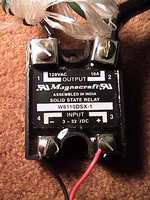
One solid-state relay
(you choose the amperage to suit, I used 10 Amp / 120V,
US$6.50 used).
A DC power supply (anything from
5 to 9V DC is fine, I used one from an old
"DiskMan").
One power-strip.
One
"Bread Board" (We will build our little circuit on this,
US $3 or less).
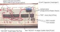
Four chips, some jumper wires of
various lengths, one capacitor, and two
resistors.
(See picture for specifics about US $3 or less).
Two wires approx 1 (use some cord from the DC
power supply mentioned above).
This is going to
be so easy, you won't believe it; they charge US$90 for
these in many Grow shops!
Note that EXACT
product codes are not important in selecting circuit
parts. But, what IS important is for the numeric part of
the code to match mine and for the number of pins to be
the same. For example, if you found a 16PIN "TC4013BP"
that would be fine even though the one I have says
"TC4013BF". The capacitor can be any type, but if you
get a polar one
like I did, make sure it goes in the
proper direction. The resistors don't
matter so
much, just get the res values correct.
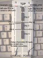
Setting up the breadboard
The Breadboard has two sides, which are electrically
insulated from each other.We will call the left side
GROUND and the right side POWER. We supply power and
ground to the board by plugging our DC Power supply
leads into bottom of the board (as shown). I recommend
soldering these connections to pieces of (more rigid)
jumper wire. You must match the positive wire from the
power supply to the positive (right) side of the
breadboard, and the negative lead to the left side.
Usually, the positive wire will look different (e.g.
have a white stripe like mine). The outermost holes on
each side of the board are used to distribute power and
ground (respectively) to an entire row of the board (I
have wired the
first row to both power and ground
sides in the photo below to illustrate this).
The chips have either 8 or 16 pins each. The
pins are numbered counter-clockwise (from bottom left of
chip) as shown.
Building
You may
connect the power and ground connections from the DC
power supply anytime but DONT PLUG IN BOARD DURING
ASSEMBLY!
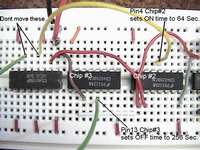
Note: When putting on the chips
exact row positions dont really
matter, just as
long as the chips go in the order specified and are
"down
the middle" of board, with lettering READABLE
FROM THE GROUND SIDE.
Install all the chips
[refer to previous picture]:
Chip#1 is the 555
timer chip.
Chip#2 = 4020B counter chip.
Chip#3 = another 4020B chip.
Chip#4 =
4013BF dual D-type Flip Flop.
Note: We will only
use one side of the "dual" F.F. I used a dual because it
was available (and commonly found).
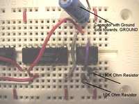
Wiring bottom chips
Note how pin8 on Chip#3 got its ground connection
from a different row. You can get Power or Ground
connections (respectively) from anywhere on the outer
pin columns.
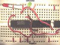
Note the optional LED's. The green
taps into pin1 on chip#4. This LED will show when the
timer is ON (helps check things). The Green LED's other
leg plugs into the Ground (as shown). The Red LED will
indicate when the timer is in the OFF state. It taps
pin2 of Chip#4, and also needs to be grounded (as
shown). NOTE: Make sure the LED's you use have
built in resistors, or else add a little resistance in
series with each LED.
The Relay
Now that the
logic portion of the timer is done. Go ahead and plug
the DC Power supply block into the wall. The green and
red LED's should alternate 2 seconds green, 2 seconds
red. This is the troubleshooting setting (we will adjust
ON/OFF times later).
Connecting the
relay:
The Solid State relay has two ends, the
DC control end, and the AC power end. ***Caution***
AC current can kill you, so please be careful. Make sure
the power strip is UNPLUGGED.
We begin by
slicing through the outer plastic of the Power Strip's
insulation, about a foot or so from the plug. Peel back
the insulation to reveal three wires (white, green, and
black). The black one is the POWER wire, the one we will
splice into the AC side of the relay. Cut the black wire
and cut and peel back some insulation from each cut end.
Make a small loop on each cut end, and screw down these
loops under the relay's screws (AC end). [See picture
for details]
Connect two small (8-12") pieces of
wire [see parts list] to the Relay's DC
power and
ground screws. Tape up the entire relay (especially
the AC end) with black electrical tape (or duct tape).
This will prevent any contact shorts and improve
safety.
Plug in the Negative (black) and
Positive (red) wires from the relay to where the GREEN
LED was before (as shown). Note that I have soldered the
ends of these wires to pieces of jumper wires (again,
for more rigid connections).
Note that I have
replaced two key wires from previous pictures with the
YELLOW and GREEN wires (for clarity). Leave these wires
connected at chip #4.
To Set ON/OFF times:
Chip #3 controls OFF time.
Chip #2 controls
ON time.
To change these times, simply plug the
Yellow or Green wires into other pins (on Chips 2 and 3)
as follows:
The following times are valid for
chip 2 (ON time) and chip 3 (OFF time):
| Pin # |
Schematic Pin
|
Delay Time
|
| |
|
|
| 9 |
Q1 |
2 sec |
| 7 |
Q4 |
16 sec |
| 5 |
Q5 |
32 sec |
| 4 |
Q6 |
~ 1 min |
| 6 |
Q7 |
~2 min |
| 13 |
Q8 |
~ 4 min |
| 12 |
Q9 |
~ 8 min |
| 14 |
Q10 |
~ 17 min |
| 15 |
Q11 |
~34 min |
| 1 |
Q12 |
~ 68 min |
| 2 |
Q13 |
~ 2 hr 15 min |
| 3 |
Q14 |
~4 hr 30
min |
***Remember that
the pins are numbered from 1-16 and arranged counter
clockwise from bottom left of chip. Do not plug into any
other pins besides those listed in table above!***
Sample time setting:
To set 64 sec. ON /
256 sec. OFF, plug the Yellow wire at chip #2 into
pin#4, plug the Green wire at chip #3 into pin#13.
The board and relay could be
fastened inside of a small plastic case with holes cut
for the power strip cord ends. Make sure to keep
components from touching though. Simply plug in your
appliance into a spot on the power strip, plug in the
strip and DC power supply, and set the ON/OFF times.
Here's the schematic of the completed cyclestat.
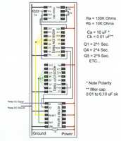
Be sure to add a filter
capacitor as the schematic indicates (not shown in
photos) to ensure proper timer functioning.
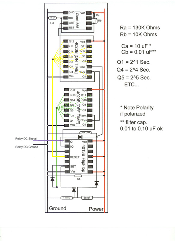
TIMER IMPROVEMENT
Below is the
updated timer layout, featuring an "automatic on"
function that restarts the timer in the ON position when
power is applied. The resistance/capacitance values on
the RC circuit are subject to what works. (The stated
values worked for me, It's all about resetting the chips
for long enough time intervals when power up occurs --
play around to find what works best for your timer.)
Shown Values:
Res. at bottom (added
RC circuit) = 1K ohm
Res at middle = 10K ohm
Cap. at bottom (RC circuit) 68 uF.
|


