Contributed by:
ranger2000
Submitted: 25-07-2003
 Introduction:
 Every
serious growing box needs cooling. Most of us use air
cooling because it is cheap and very effective. The
following steps are used to design a simple fan-cooled
box.
This method does not cover active cooling with
air conditioning systems or 'CoolTube' designs. It is
for grow chambers where the walls are approximately
equal to the light pattern, totally enclosed for airflow
control, and do not have large radiant heat into or out
of the box. Your mileage may vary some for these
reasons.
I also picked sane defaults for growing
conditions. The formulas
diverge if you get too far out
of plant growing range. You should be very safe if you
are within about 40 to 150 degrees F and 20% to 90%
humidity ranges (those are just guesses). Atmospheric
pressure was picked as sea level and doesn't really
affect anything until about 5,000 or 8,000 feet
depending on how accurate you want to get. If extreme
conditions apply to you, there may be other FAQ entries
with the entire full blown set of
pressure/temp/airflow/humidity parameters.
Design 1) Start at the
beginning and design this right! Before you ever buy or
cut anything for your new project, determine the highest
temp (in F) your intake air will ever be when lights
run. Get a thermometer and measure it to make sure you
have a good value. Call this
T(inlet)
2) Use these formulas to determine
difference in temp you can tolerate. 81F (27F) is about
the optimal for growing, 86F/30C on the higher end.
Tdiff = 81F - T(inlet) (English)
Tdiff = 27C
- T(inlet) (Metric)
3) Add up wattage for
all power in your box. Lights, pumps, heaters,
humidifier, radio, coffee pot, whatever. Add it all up
and call it Watts. This will make your number worst-case
and therefore a conservative value.
4)
Compute the absolute minimum fan power you will need
using the following formulas. This is the minimum fan
rating you must have to achieve your temperature goals.
You will have to increase fan power to compensate for
duct constrictions, small inlets, carbon scrubbers,
screens, or other items that block airflow.
CFM
= 3.16 x Watts / Tdiff (English)
CMH = 2.98 x Watts
/ Tdiff (Metric)
The formulas are almost
identical, due to the counteracting effects of
converting airflow from CFM to CMH, and converting temp
from Fahrenheit to Centigrade.
formulas can be found on this web
page: (This web site also lists the
above formula and uses a constant of 3.16 as shown
above)
5) If you have more than one fan,
they should be mounted side-by-side rather than inline
if you want to add their different CFM ratings.
For inline fans, use the lowest airflow rating
of all fans in the path. A fan on the inlet and a fan on
the exhaust of the box are considered inline fans. Fans
inside the box should not be counted for airflow but
must be included in wattage. A standard computer fan is
normally right around 30 CFM (50 CMH).
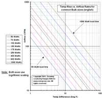
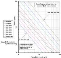
The two
lookup charts solve this equation for common lights.
Make sure you get the proper one (English or metric).
For those of you who are wondering if you did this
right, here are a few numbers in English units :
| Watts |
CFM |
Tdiff |
| 70 |
30 |
7.4 |
|
| 150 |
30 |
15.8 |
| 150 |
60 |
7.9 |
| 150 |
130 |
3.6 |
|
| 250 |
130 |
6.1 |
| 250 |
265 |
3.0 |
| 250 |
400 |
2.0 |
|
| 400 |
130 |
9.7 |
| 400 |
265 |
4.8 |
| 400 |
400 |
2.7 |
|
| 600 |
265 |
7.2 |
| 600 |
465 |
4.1 |
|
| 1000 |
30 |
105.3 |
| 1000 |
265 |
11.9 |
| 1000 |
465 |
6.8 |
Note: a 30cfm
computer fan is trying to cool a 1000w HID bulb, in the
3rd from the last row, as an extreme example
If
you are adding any carbon scrubbers or extensive
ductwork, this is where you add to the fan size to
account for air pressure losses. You have to move this
many CFM, or the numbers don't come out right. The
deciding factor for these items depends on your exact
configuration and is beyond this discussion.
6) When your box is built, buy a
thermometer and measure the air blowing out of the box
(temp probe or thermometer should be in the air stream
just after the fan, outside of the box enclosure) and
the temp of the air entering the box (again, from
outside the box perimeter). Make sure there is no direct
light shining on the thermometers to ruin the
measurement. DON'T MEASURE THE TEMP INSIDE THE BOX
YET!!!! It's best to do this with 2 thermometers or a
single thermometer with a remote probe. Cheap
thermometers don't work well because they aren't very
accurate. If you only have cheap thermometers, use the
same one for all measurements to avoid accuracy issues.
7) Subtract your measured inlet from
measured outlet temp. Compare to Tdiff from above. Is
your measured difference as good or better than your
estimated from step 2? If not, go find out why. Your
problems are probably:
A. Heat source you didn't
account for (the ballast?)
B. Your fan is overrated
C. You have blocked airflow
D. Your temperature
measurement was inaccurate
E. Air leaks into the box
(especially around the fan!) that ruin efficiency.
8) Once you get your measured temp
difference equal to step 2, measure temps inside the
box. Don't let the light shine right on the sensor, it
will give faulty readings!! Use a light shield made from
a tin can or something. If temps inside the box are
higher than your exhaust temp at a reasonable distance
from the bulb, you have air circulation problems inside
the box. Get some kind of fan to stir up the air in
there or look for airflow paths that allow air to travel
from inlet to exhaust without spending any time in the
box.
9) Always monitor the temperature
difference between inlet and outlet temps every time you
water the plants. If it varies much more than a degree
or two, find out why. I use digital indoor/outdoor
thermometer. It tracks high and low for both locations,
outdoor probe is on a long wire, $14 at Kmart. No part
of the thermometer is inside the box, just in the
measuring air blowing in and out from the outside.
Please note that conversion values have been
slightly rounded off to make this easy. Using the metric
and english formulas will yield slightly different
answers if compared. The difference should be less than
one percent and can be ignored.
You can use the
two load graphs attached if you prefer to do
calculations visually rather than using the formulas
listed above. Find the line for your light wattage and
ignore all others. Each axis is logarithmic, make sure
you count along each axis properly. The formulas listed
in step 4 were used to make the graphs.
Sidenotes: You can measure your
fan airflow very accurately if you use a standard
trouble light with a 60 or 100 watt bulb in it. These
are very good test loads for calibrating things.
Just put it in and work through the formulas using a
good thermometer to determine airflow. If you doubt the
accuracy of your bulb and are really anal about it, you
can calibrate the bulb against your electric meter over
several minutes. You could also stick in a different
brand of bulb at the same wattage and compare results. I
haven't tried this, but I would just trust the bulb
until proven wrong.
Testing and measuring
duct losses: Ducting losses are hard (to
measure) because they rely on knowing your duct material
coefficients. You
can measure the losses in the
duct after it is built and running, if that would help.
You could measure a test section to calibrate that
material, then extrapolate. Here's how:
Take a
known fan (or the fan you will be using) and blow it
into a plenum that has a heat source and some of your
sample duct mounted to it. To do this, you need a
trouble-light or other low wattage known source and a
cardboard box to put it in, then mount the fan on the
box and stick the duct on the other side.
Calibrate the box by measuring temps without the
ducting, then compute CFM. Add the duct, measure the new
temp, compute the new CFM. The difference is duct loss.
Basically, use temperature and wattage to measure
airflow and compute duct loss.
If you have an
existing room, just measure inlet and exhaust temps, add
up the watts, and then compute effective airflow. I just
did this for my box and it's pretty much dead on. I
think it varies by about +/- 0.2 DegF for 150 watts and
two computer fans.
Once you have the value for
your ducts, you can estimate loss by adding up the
length. We would have to come up with adjustment for
going around corners.
I once saw a Mech Eng.
book that had different shapes of pipe listed (Tee, 45
Deg bends, 4-way branches, Y-branches, etc) and then
gave an equivalent length of straight ducting they add
for flow resistance.

